1969 Traveler hilo Help request & data

69hilo2

Senior Member
Joined
Jun 25, 2013
Messages
277
Location
near Tampa, Fla
Well off this goes. Several years ago my wife and I bought this hilo. As Is Where Is. No manual no anything. Well got it home and this led to that. My wife and I build a house. We designed it and really did a lot of the work. So the hilo sat. Now I'm thinking that the house is almost done and it's time for the hilo.
From the title find it's a 1969. From this website I download the 1969 manual.
http://www.hilotrailerforum.com/f49/owners-manual-1969-bon-voyage-836/
Also the 1971 it has some more details that you can review also.
http://www.hilotrailerforum.com/f49/1971-hi-lo-14ft-owners-manual-single-axle-2196/
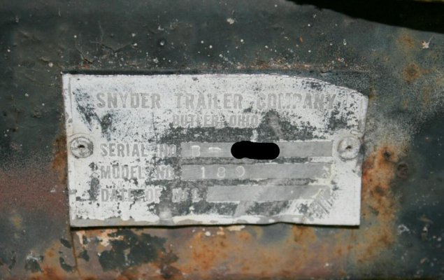
Find the tag on the right front of the frame and get a few more details.

Current problems that I'm going to share. Also data as it's found.
So on with the picture show. New site, old dog, that's me so lets try to post a lot of pictures and see what happens.
Well if it goes the way that I think it will.
1st is the Logo -- Traveler
2nd Frame tag
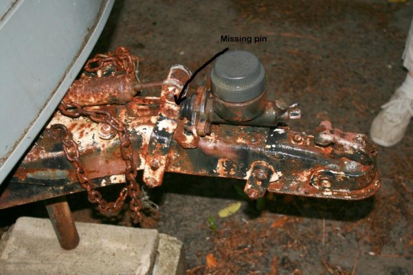
3rd front part surge brake showing missing pin
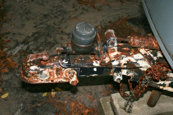
4th other side surge brake

All of this stuff I have a basic handle on. Need help in the next post

Later Tim 1969 hilo
 

Attachments

  • 7.jpg
    7.jpg
    83.7 KB · Views: 54
  • 8.jpg
    8.jpg
    95.6 KB · Views: 52
  • 1.jpg
    1.jpg
    95.1 KB · Views: 63
  • 1a.jpg
    1a.jpg
    95.5 KB · Views: 53
Last edited:
part 2

Major problem areas
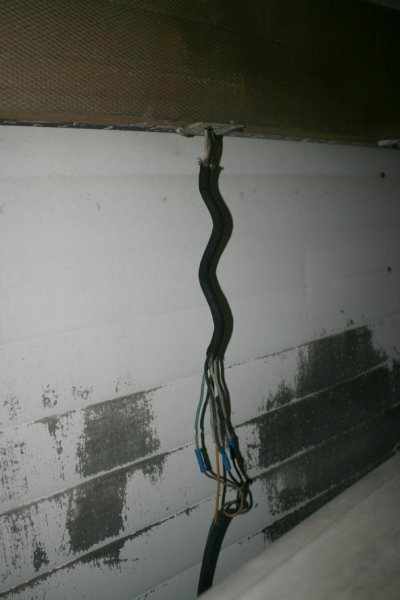
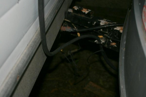
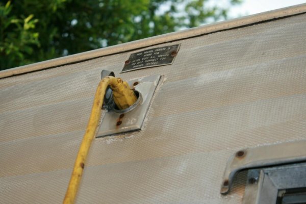
Wiring -- Wiring... Look at the pics. Someone really worked over the front cable several times at least.
Question is should I take the front area off the top to see and check out where and how the cable goes?

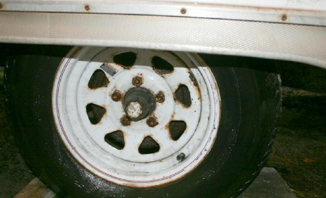
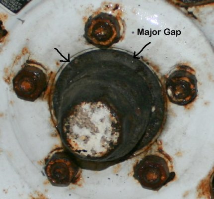
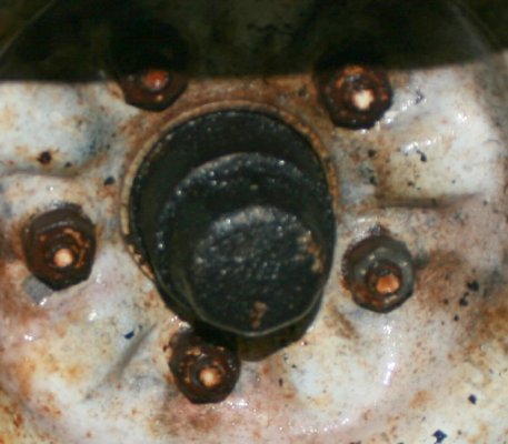
Wheels (not tires / which I'll replace) Look at the pics. See how the inside of the wheel does not some near the axle on the one. I believe that the last owner replaced one with an incorrect wheel and tire. This scares me. Does anyone know anything about the wheels?? I could guess 5 lug (Ford??) size is easy to measure. Ford Chev or hilo special wheel. Help??
Last wheel pic is of the one that I think came with the hilo
Ok, have a few minor problems after that but I can handle those.

On with the picture show. Ok

Later Tim
 

Attachments

  • 2a.jpg
    2a.jpg
    87.5 KB · Views: 55
  • 3.jpg
    3.jpg
    52.5 KB · Views: 47
  • 6a.jpg
    6a.jpg
    93.1 KB · Views: 46
  • 6c.jpg
    6c.jpg
    81.1 KB · Views: 48
  • 6.jpg
    6.jpg
    80.4 KB · Views: 44
Last edited:
part 3

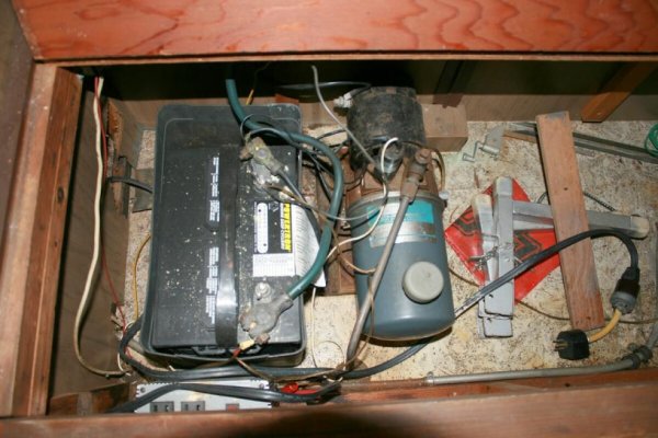
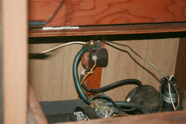
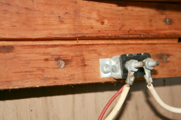
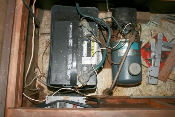
On with the show. Ok, I'm good with most of the inside wiring that you will see in the next few wiring pics, so these pics are for other folks that need to see what mine looks like. Yes I'll go in later and make a few things look better. Last pic shows an inverter that someone put in after market. Down under it are battery clamps that you clamp on the battery terminals when you need ac power. Also frig was replaced to a 110 volt frig no gas.

Later Tim
 

Attachments

  • 4.jpg
    4.jpg
    94.6 KB · Views: 57
  • 4a.jpg
    4a.jpg
    83.8 KB · Views: 54
  • 4b.jpg
    4b.jpg
    86.8 KB · Views: 52
  • 4c.jpg
    4c.jpg
    96.2 KB · Views: 53
part 4

My dog that wants to go camping. It took about two weeks to talk him into the camper. About the same time that it took to talk him into jumping into a kayak and go kayaking with us. Have you ever kayaked with an 80 pound dog moving around? It's lots of fun. Really he seems to enjoy it.
I'll try to add more info and data to this thread as I get help from other and find things.

Later Tim & Nancy Owners of a 1969 hilo with a nice dog.
 

Attachments

  • dog inside.jpg
    dog inside.jpg
    85.8 KB · Views: 18
Last edited:
Dogs & canooes

5 years ago my two dogs (Boxer & Sheppard) would ride with the wife and I. It really was too risky as they'd shift left/right, often together ... and nearly dump us. Finally had to ban that.

Same thing though, at first they were reluctant to join us, then couldn't keep them away.

Now, to keep this on-topic, I don't envy you, that's gotta be a lot of work ahead of you.
 
Major problem areas
Wiring -- Wiring... Look at the pics. Someone really worked over the front cable several times at least.
Question is should I take the front area off the top to see and check out where and how the cable goes?

For that wiring, it is hard to tell, and I am not the most experienced person on the HiLo wiring schematic, but it looks like that is the umbilical cord that goes from the lower portion of the trailer to the upper section to provide power to your upper portion light etc...? Like I said don't hold me to that answer being correct.

Anyways, I would recommend trying to ohm out the cable and try to find the locations where it leads to, like remove one of those butt connectors outside the trailer and measure from that point to say a light fixture or something in the upper portion of the trailer to determine if they are a common connection. This will hopefully help you find where everything else is tied into the upper portion of the trailer. If you look around in the manual section here there is some electrical schematics that may be useful also, just not sure if they will be relevant to a 69 Hilo? But they may help you.

Also, I would highly recommend at the least point is to remove those butt connectors clean them up for any corrosion and re-crimp with new connectors and wrap them to provide protection from the elements such as water.
 
Tim,
On your rig, where do you plug in your 110AC shore power cord? Our 1969 didn't have a permanently wired shore power cord. It was simply a heavily insulated 15amp cord that plugged into a "male" outlet on the trailer. The "male" end on the cord going to the power source.
Incidentally, the "male" outlet on our HiLo was high on the upper half wall, on the side opposite the entry door. Inside the trailer, in close proximity to where the "male" outlet was externally positioned, was a breaker box in an overhead cabinet.

On ours, The original HiLo 110AC was an entirely separate wiring system, not requiring any kind of converter/transformer/inverter. 110AC lights were separate single bulb fixtures that plugged into 110AC outlets in the ends of the upper cabinet (s). The 12VDC system and lights came directly from the battery through a multi-conductor coil wire that mounted externally between a Junction box on the tongue, and a connection point under the front edge of the upper half. Being coiled, it therefore wouldn't drag when the trailer roof was down.

Hoped I've helped increase your knowledge, and not your confusion!
Jim
 
Input

PappaP
Thank you for your input. I'm planning to open the siding in that area and go in and replace that cord that you see with a new one. As far as a electrical schematic most of it is covered in the posted 1969 owners manual.

Jim
I think that we have the same 110 volt set up, see pic. Only have one of those plug in 110 lamps. Only came with one. Hard to find I'll bet. Breaker box, same location with 2 -20 amp fuses inside. Some past owner put in an AC window unit in the back and it's plugged into one of the circuits.
From what I can see the water pump power is running off the battery that raises and lowers the hilo.
The inside 12volt lights in yours ran from the outside power source like the truck connection? Or from the inside battery.
I believe that the inverter was put in after the gas/ac frig was replaced with a 110 only frig.

What do think of my trying to open the siding in the top front below the window that covers where the coiled wire comes in from the outside?

Thanks Everyone. Any Thoughts on what to replace the wheel with??

Later Tim
 

Attachments

  • 2.jpg
    2.jpg
    90.9 KB · Views: 31
Tim,

The inside 12VDC lights work off the onboard battery. Now if the TV charging wire is properly installed, and you have a good ground back to the TV, the 12VDC lights will also work from that source.

You mention the water "pump." Original HiLo setup was actually a little air compressor that would pressurize the water tank (galvanized steel) to push the water to the tap. Has yours been converted to a "demand" type pump? If not, I totally recommend it...much lower battery draw, and actually provides a better water pressure.

Please note that these HiLo were fairly advanced for their time. Most 1969 brands of trailers had a ice box, a mounted propane lamp instead of electric lights, and a little hand pump to draw water to the sink. Now days they seem primitive compared with the fancy conveniences of modern trailers.

I wouldn't open the skin. First pull the cover off the little connection point, and check continuity using a VOM. Even easier get a couple of 6 volt dry cell batteries, wire them in series, and connect one wire at a time and see what lights up!

Jim
 
TV is the common Tow Vehicle abbreviation in the RV world.
 
Thanks for more info

Jim
Thanks for more info.
You stated """Original HiLo setup was actually a little air compressor that would pressurize the water tank""".
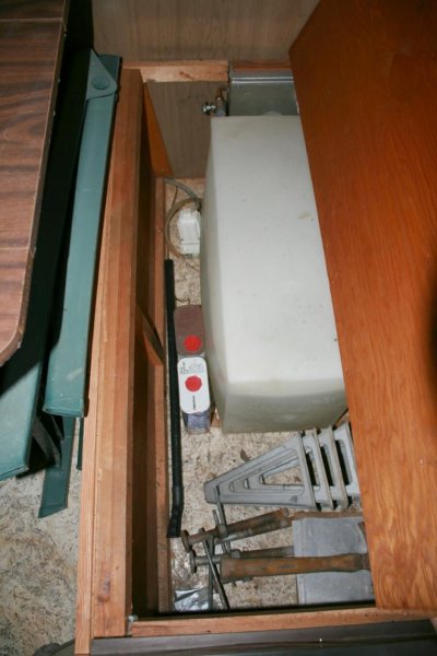
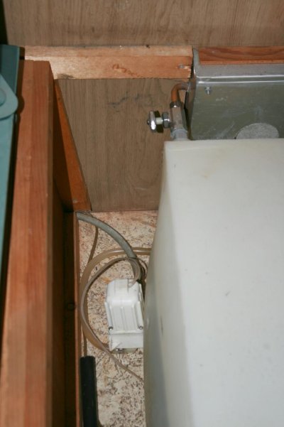
That could be it. Till I get a new battery for the inside I'm still guessing at a few of the things. We have a plastic tank, see pic. A switch in the cabinet under the sink, which I guess makes the water action work, either pump or air pressure. Just reviewed the pics myself. Looking at it I'm guessing mine is a pump system. Looks like water intake on one side and a output tank to the other side. Could be wrong. Really will not know till I hook up a battery to everything.

Reason that I'm thinking of pulling the skin off is to make sure that the new wire is held firmly on the inside without putting pulling pressure on the electrical joints. Also want to make sure that if I add a box on the outside I don't screw into an wires. At one time I had almost all of the 12 volt lights work except in one damaged corner. Noe sure what one of the last owners did, but they crumpled the upper drivers side corner. Most of it is pulled out and looking ok.

How does the upper 12volt lighting system link (wired) to the bottom half that has the battery? Long wire that slides up and down with opening and closing or??

Thanks for any input.

Later Tim & Nancy and the dog.
 

Attachments

  • 10.jpg
    10.jpg
    89.9 KB · Views: 47
  • 11.jpg
    11.jpg
    83.4 KB · Views: 42
TV

Thanks Rich for confirming that TV is Towing Vehicle.
Had me thinking for a minute also.

Later Tim & Nancy and a dog that wants to go camping again.
 
Hi Tim,

Regarding your electrical system: you never really wrote (or perhaps I missed it), if or not, the various components of your AC and DC systems actually work.

If you decide to replace the "umbilical cord" looking wire connecting the upper/lower half, check out the coiled cords found at commercial truck parts suppliers. They are more expensive, but WOW are they good! Plus in trailer duty, it will last forever, and come in a heavier wire gauge than that typically found at an RV supplier. When selecting the coiled wire, select one with two or three conductors more than the original.

Why? Well here is a sidebar answer: Hi-Lo in those days grounded the upper half DC system to the lower half (and chassis frame), using the galvanized lift cables. The system worked great for years, until the galvanizing zinc built up enough corrosion (in this case a white powdery stuff), to become an electrical insulator. When that happens the DC stuff in your trailer doesn't work so well anymore (in my case, everything stopped working.

So when you choose the new coiled "umbilical" cord, use two of the extra conductor wires to create a permanent new ground for the upper half. Presto, all your DC stuff will work again, better than before!

Jim
 
Tim,

Looks like you made your last two entries while I was still writing mine... Now I understand that everything in your DC system works. That is GREAT!

When I had my umbilical cord apart, I remember that there was more than adequate strain relief to keep the cord from yanking out. Plus the coil of the new cord will remove virtually all stress, other than the actual weight of the cord itself. Peeling aluminum back and then restoring certainly can be done. But also carries a few fit and appearance risks. I would definitely install the new wire and see first, how we'll it fits in, before opening the wall.

Jim
 
Jim
Thanks for more info.
You stated """Original HiLo setup was actually a little air compressor that would pressurize the water tank""".
That could be it. Till I get a new battery for the inside I'm still guessing at a few of the things. We have a plastic tank, see pic. A switch in the cabinet under the sink, which I guess makes the water action work, either pump or air pressure. Just reviewed the pics myself. Looking at it I'm guessing mine is a pump system.

The plastic tank is probably vented and can't be pressurized as such.
 
Thanks

Thanks Jim and RichR for your input.
Jim
110 volt systems seem to work just fine.
12 volt systems worked fine last time I had a good battery in the hilo. Hope to gather enough money together to get a new one next week. Then I'll know a lot more.

RichR
Well the tank could be pressurized. Enough to force water through the system, well maybe not. But looking at pic 10 4 posts above you see a valve upper left corner that valve vents to the outside. On one to the first trips into it I opened the valve and could hear the air release. Still think that is a water pump in the same pic.

Question everyone
When I go to jack up the side of this single axle hilo to remove a wheel to check the brakes etc. Where is the jack lift point?? I have not seen anything about that in an manual. Normally I would place the jack where the spring meets the axle and use that as a lifting point. Thoughts??

Later Tim & Nancy and a dog that wants to go camping again.
 
Well the tank could be pressurized. Enough to force water through the system, well maybe not. But looking at pic 10 4 posts above you see a valve upper left corner that valve vents to the outside. On one to the first trips into it I opened the valve and could hear the air release. Still think that is a water pump in the same pic.

That does look like a water pump but not like a normal RV type pump. Do you suppose someone added the valve to pressurize the tank? Then there would have to be a way to add air pressure somehow. Or by adding water to the tank under pressure it would compress the air already in the tank.
 
Last edited:
Tank

RichR wrote """Do you suppose someone added the valve to pressurize the tank?""" -- no. The copper tube that you see going from valve goes through the wall to outside and is just cut off at the end, no fitting. I believe that the valve is there to vent to the outside to keep the tank avoid having negative pressure happen in the tank. Also I don't believe that the tank could hold enough pressure without popping.

Thanks

Later Tim & Nancy and a dog that wants to go camping
 

Attachments

  • 3.jpg
    3.jpg
    78.5 KB · Views: 23
Tim,

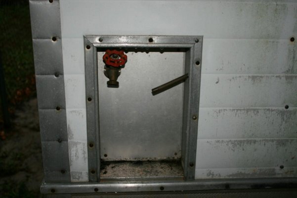
The spigot and pipe in the recess isn't at all like our 1969. The neat aluminum alcove is identical, but in the very middle of ours is a tank fill spout. Our original equipment spout is a complicated gizmo with a garden hose connection on the bottom, and about a three inch diameter screw on cap. The cap actually contains a pressure gauge. Also mounted on the side wall, of the spout, is an air fitting like that found on a bike tire. That came in handy if you wanted to pressurize the water tank while filling the TV gas tank. Our galvanized tank doesn't have an overflow pipe.
Honestly, the spout set-up isn't particularly good for filling the tank. The angles are wrong and the thing is too far recessed in the alcove for efficient pouring.

Jim
 

Try RV LIFE Pro Free for 7 Days

  • New Ad-Free experience on this RV LIFE Community.
  • Plan the best RV Safe travel with RV LIFE Trip Wizard.
  • Navigate with our RV Safe GPS mobile app.
  • and much more...
Try RV LIFE Pro Today
Back
Top