|
|
02-16-2016, 06:34 PM
|
#41
|
Senior Member
Join Date: Feb 2016
Location: Alabama (roll tide!)
Posts: 100
|
Quote:
Originally Posted by JackandJanet
Well, that's where the Master Switch and the Lift Switch are supposed to be. The lift switch in my trailer is white and is spring loaded to the center (neutral) position. The Master Switch is black and has three positions - Up (interior), Middle (travel) and Down (Lift System activated). It will stay in any of those three positions.
Yes, DO trace that red wire! And, see my post just before your last one.
- Jack
|
Good to know. Time to get on Amazon and start finding those switches. Thanks.
__________________
|
|
|
02-16-2016, 06:36 PM
|
#42
|
Moderator
Join Date: Feb 2010
Location: NW PA
Posts: 3,386
|
Please note: The wiring diagram showing the wiring from the motor has a mistake. The black #8 wire from start should go to the left terminal on CB-1, not on the right terminal. http://www.hilotrailerforum.com/f51/...ry-wiring-116/
__________________
__________________
My Great Wife Joyce
2018 Jayco Jay Flight 21QB
Formerly owned 1705T and 2310H
2012 F150 4X4 SuperCrew EcoBoost w/Leer Cap
Reese WD Strait-Line Hitch
Amateur Radio K3EXU
|
|
|
02-16-2016, 11:35 PM
|
#43
|
Site Team
Join Date: Jul 2010
Location: Pine, AZ
Posts: 4,687
|
Quote:
Originally Posted by RichR
|
Interesting, Rich. My trailer has that wire connected to the RIGHT terminal, as is the black 10 gauge wire to the tongue lift motor (through an inline fuse). But, the black 10 gauge battery charging wire from the trailer plug goes to the LEFT terminal and, the blue refrigerator wire goes to that left terminal too. Finally, my trailer breakaway is attached to the left terminal of CB#1 too.
I doubt it really matters, as long as the circuits are all protected somehow.
I don't think the people assembling our trailers really followed a checklist.
And motorpig, you MIGHT find switches that would work in ACE Hardware, or an electrical supply store if you can't find them online.
- Jack
|
|
|
02-17-2016, 08:27 AM
|
#44
|
Moderator
Join Date: Feb 2010
Location: NW PA
Posts: 3,386
|
Quote:
Originally Posted by JackandJanet
Interesting, Rich. My trailer has that wire connected to the RIGHT terminal, as is the black 10 gauge wire to the tongue lift motor (through an inline fuse). But, the black 10 gauge battery charging wire from the trailer plug goes to the LEFT terminal and, the blue refrigerator wire goes to that left terminal too. Finally, my trailer breakaway is attached to the left terminal of CB#1 too.
I doubt it really matters, as long as the circuits are all protected somehow.
I don't think the people assembling our trailers really followed a checklist.
And motorpig, you MIGHT find switches that would work in ACE Hardware, or an electrical supply store if you can't find them online.
- Jack
|
Maybe our trailer is wired wrong. But as you said, it may not really matter as long as the circuits are protected. I think it would be preferred as in the diagram in that the battery would be direct to the breakaway switch and the tow vehicle connection in case the breaker fails. The tongue lift has its own inline fuse. The only thing I question is that in the diagram is the power going to the rest of the trailer goes through two circuit breakers where only one would be sufficient. Am I right?
__________________
My Great Wife Joyce
2018 Jayco Jay Flight 21QB
Formerly owned 1705T and 2310H
2012 F150 4X4 SuperCrew EcoBoost w/Leer Cap
Reese WD Strait-Line Hitch
Amateur Radio K3EXU
|
|
|
02-17-2016, 10:47 AM
|
#45
|
Site Team
Join Date: Jul 2010
Location: Pine, AZ
Posts: 4,687
|
Quote:
Originally Posted by RichR
Maybe our trailer is wired wrong. But as you said, it may not really matter as long as the circuits are protected. I think it would be preferred as in the diagram in that the battery would be direct to the breakaway switch and the tow vehicle connection in case the breaker fails. The tongue lift has its own inline fuse. The only thing I question is that in the diagram is the power going to the rest of the trailer goes through two circuit breakers where only one would be sufficient. Am I right?
|
You are totally right. That was actually fixed in my trailer too, but I didn't mention it in my last post. There is a short 8 Gauge black wire in the diagram running from the left terminal of CB-1 to the left terminal of CB-2. In my trailer, that wire originates from the RIGHT terminal of CB-1, which effectively connects it directly to the +12V terminal of the battery, bypassing CB-1.
I suspect there are two 30A circuit breakers so that two high amperage draws can exist together (for a short time) In my case, the refrigerator is powered through CB-1 and the rest of the trailer gets its feed through the Master Switch which receives its power through CB-2.
Disregard this post! I think I'm losing what little grey matter I have left. I'm going to try to create a readable drawing of the actual wiring to the circuit breakers in my trailer and will post it here. I made pen and ink changes to the circuit diagram, which I've been referring to in this thread, and somehow, I got it WRONG!
- Jack
|
|
|
02-17-2016, 02:45 PM
|
#46
|
Site Team
Join Date: Jul 2010
Location: Pine, AZ
Posts: 4,687
|
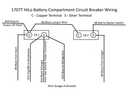
A Corrected Circuit Breaker Wiring Diagram
OK, this is correct (at least for my trailer) and should work for any other trailer with similar components. The only changes in the wiring I can find are at the two circuit breakers in the battery compartment, so that's the only part I'm showing.
I reoriented the wires in the diagram so there would be no wire crossing, which can be confusing. All wires carry +12V battery voltage.
Your trailer may have slight differences, but if you examine your wiring and this diagram, I think you will find they essentially are equivalent.
Sorry for some of my confusing posts earlier! And, I've added this diagram to the 2306 Primary Wiring thread in the Reference Library.
- Jack
|
|
|
02-17-2016, 03:59 PM
|
#47
|
Moderator
Join Date: Feb 2010
Location: NW PA
Posts: 3,386
|
Jack, I think you have it well nailed.
As we can see, the boys at Hi-Lo kind of did there own things. They weren't necessarily wrong but just different in the way they did things.
__________________
My Great Wife Joyce
2018 Jayco Jay Flight 21QB
Formerly owned 1705T and 2310H
2012 F150 4X4 SuperCrew EcoBoost w/Leer Cap
Reese WD Strait-Line Hitch
Amateur Radio K3EXU
|
|
|
02-17-2016, 04:09 PM
|
#48
|
Senior Member
Join Date: Feb 2012
Location: Wisconsin
Posts: 1,256
|
So does this jibe with what you guys concluded in our discussions this summer?? I still have an isolated wire with an inline fuse running to battery from the power jack and by-passing the breakers. Which works, and in some ways seems to make perfect/simple sense.
Rick
__________________
2201 TL
2010 Nissan Titan king cab SE
4x4
|
|
|
02-17-2016, 05:18 PM
|
#49
|
Site Team
Join Date: Jul 2010
Location: Pine, AZ
Posts: 4,687
|
Quote:
Originally Posted by hilltool
So does this jibe with what you guys concluded in our discussions this summer?? I still have an isolated wire with an inline fuse running to battery from the power jack and by-passing the breakers. Which works, and in some ways seems to make perfect/simple sense.
Rick
|
Yes, Rick, I think it does. The gray wire coming from the left terminal on CB-1 has an inline fuse in it on the way to the power jack. Since the battery feed also attaches to that post, the circuit breaker is being bypassed and is just being used as a convenient attachment point. The grey wire COULD have been attached directly to the positive terminal of the battery, as it sounds like yours is.
- Jack
|
|
|
02-20-2016, 08:09 PM
|
#50
|
Senior Member
Join Date: Feb 2016
Location: Alabama (roll tide!)
Posts: 100
|
Video of it in action....
Ok, before I start wiring switches into their orginal place I have some question. I've been playing with the two toogles the guy had wired in the battery box. One Toggle he has is for power. The other is another toggle (not three step with spring sending back to neutral). If I engage the second toggle I mentioned it allows power to feed into the magnetic valve and will allow the camper to raise if you flip the main power toggle. If you flip the second toggle at any time the lift will stop and it will start lowering again (being that the magnetic valve is no longer energized (or maybe the opposite, I havent ran a test to see if toogle on is actually giving or cutting power). OK, are you suppose to be able to lower the camper without power? Seems like the videos I see, you hear the pump running when the camper is being lowered. Doesn't matter if I've got power to the main switch or not. As soon as I flip the second toggle the camper will start coming down. If I flip it again it reverses the magnetic valve and the camper will stop coming down. Then If I flip the first toggle again and give the pump power, the camper starts going back up. I do plan on getting that spring loaded switch but Does this sound like the way it should be wired so far? Once I know for sure I'll start rewiring the switches in their original location. Thanks.
Here is a link to a video of it in action.
https://drive.google.com/file/d/0Bwj...ew?usp=sharing
|
|
|
02-20-2016, 09:19 PM
|
#51
|
Moderator
Join Date: Feb 2010
Location: NW PA
Posts: 3,386
|
The pump does not run when lowering, the switch only activates the hydraulic release valve, or whatever it's called What you will need are two (SPDT) single pole double throw switches, center off. The main/master switch can be a three position rocker switch with a heavy duty rating because one position will carry all the 12 volt trailer circuits. The up/down switch is a momentary on /center off/momentary on and it can be a lighter duty rating because it only activates the solenoids. If you still have a Radio Shack in your area you could look there. Also, look on www.allelectronics.com or http://www.allelectronics.com/make-a...switch/1.html# and http://www.allelectronics.com/make-a...-switch/1.html
The one switch is DPDT but that is okay because it is just two switches side by side, you only have to use one set of terminals and leave the other side alone.
__________________
My Great Wife Joyce
2018 Jayco Jay Flight 21QB
Formerly owned 1705T and 2310H
2012 F150 4X4 SuperCrew EcoBoost w/Leer Cap
Reese WD Strait-Line Hitch
Amateur Radio K3EXU
|
|
|
02-20-2016, 11:35 PM
|
#52
|
Site Team
Join Date: Jul 2010
Location: Pine, AZ
Posts: 4,687
|
Looks to me like the previous owner kind of created a "kludge". Not a good thing in my opinion. He's wired in TWO SPST (Single Pole Single Throw) switches in a way that simulates a single SPDT switch. So, the one that's to the left in the video opens the release valve. As long as it's off, the right hand switch will turn the lift motor on and the top will raise. I suspect, if you were to switch the release valve one to the other position while the top was raising, it would stop going up even though the lift motor was running. And, if you tried activating the lift motor with the release valve open, the motor would run but nothing would happen.
Using a SPDT switch with a center "Off" position keeps those conflicting signals from happening. And, if it's spring loaded to center, you have to be actively working the switch to make anything happen. You want a SPDT spring loaded to center switch for the Up/Down function.
Then, the other SPDT switch Rick talked about also should have a center "Off" position, that completely disables the lift/lowering function and trailer interior components. It should NOT be spring loaded The upper position delivers the power from the Red wire from CB-2 to the trailer lights, furnace, fans, etc. In the lower position, it delivers that power to the spring loaded lift switch.
The only thing in the trailer interior that is NOT run through the Master Switch is the refrigerator, which gets its DC power through the Blue wire from CB-1.
You also want those two switches next to the safety bar release lanyard so that lowering is a one-person job.
- Jack
|
|
|
02-21-2016, 09:39 AM
|
#53
|
Site Team
Join Date: Feb 2015
Location: SWFL Bonita Springs/Andrews, NC
Posts: 1,264
|
Well explained Jack. Truly, easily followed. That should help him along.
Tree
__________________
Treeclimber
2703 Tow Lite
2002 Escalade
Bonita Springs, Fl. &
Andrews, NC
|
|
|
02-21-2016, 12:19 PM
|
#54
|
Senior Member
Join Date: Feb 2012
Location: Wisconsin
Posts: 1,256
|
Ok, Jack, whats "kludge" stand for? A derivative of "FUBAR"? Whatever it is I think I like it.
__________________
2201 TL
2010 Nissan Titan king cab SE
4x4
|
|
|
02-21-2016, 12:25 PM
|
#55
|
Site Team
Join Date: Jul 2010
Location: Pine, AZ
Posts: 4,687
|
Quote:
Originally Posted by hilltool
Ok, Jack, whats "kludge" stand for? A derivative of "FUBAR"? Whatever it is I think I like it.
|
Here's a link to the definition: kludge - Bing Yes, it's a bit of "FUBAR".
I've been known to employ a few kludges in my past, but I hate to admit it.
- Jack
|
|
|
02-21-2016, 12:36 PM
|
#56
|
Senior Member
Join Date: Feb 2012
Location: Wisconsin
Posts: 1,256
|
MY my- the things I learn here. And in the OXFORD no less. Thanks- and well used in this case.
rick
__________________
2201 TL
2010 Nissan Titan king cab SE
4x4
|
|
|
02-21-2016, 06:22 PM
|
#57
|
Site Team
Join Date: Jul 2010
Location: Pine, AZ
Posts: 4,687
|
Quote:
Originally Posted by hilltool
MY my- the things I learn here. And in the OXFORD no less. Thanks- and well used in this case.
rick
|
Yup! I love the word "kludge". I taught programming for 20 years. It's commonly used to describe "awkward" code that fixes some earlier fault.
But, it certainly applies to almost any ugly repair or modification (think "duct tape").
- Jack
|
|
|
02-29-2016, 07:47 PM
|
#58
|
Senior Member
Join Date: Sep 2012
Location: McGregor, IA
Posts: 167
|
While your brains are all warmed up with wiring. My water pump quit. It works wired direct but not with the switch. The light on the pump switch goes on, then off, no pumping. Something clicks up front near water heater light goes off, cycle switch, light goes on something clicks light goes off. Switch has a red shows 12v, white ground, a black and a brown. Any ideas?
__________________
Jim
|
|
|
02-29-2016, 11:28 PM
|
#59
|
Site Team
Join Date: Jul 2010
Location: Pine, AZ
Posts: 4,687
|
Jim, no good ideas at all. That circuit is fused, and if it's blown, you wouldn't get the click and brief "On" light. Possibly, the switch itself (or the connection(s) to it) is/are faulty? I honestly cannot think of anything else to check.
But, if you cut the switch out of the circuit and simply apply 12V to the pump and it works, then the problem almost HAS to be the switch.
- Jack
|
|
|
03-01-2016, 12:36 AM
|
#60
|
Senior Member
Join Date: Oct 2011
Location: Berwick. Pa
Posts: 347
|
Quote:
Originally Posted by miniceptor86
While your brains are all warmed up with wiring. My water pump quit. It works wired direct but not with the switch. The light on the pump switch goes on, then off, no pumping. Something clicks up front near water heater light goes off, cycle switch, light goes on something clicks light goes off. Switch has a red shows 12v, white ground, a black and a brown. Any ideas?
|
That sounds exactly like how my Hot Water Heater works on gas. Turn on the switch, lite comes on HWH fires and lite goes off. I'm not trying to be smart but you are turning on the right switch? On mine the water pump switch is in with the tank gauges and the HWH switch is by itself. Even though they are close to each other.
__________________
__________________
Cheers
Garyk52
DW Judy
96 24' Hi-Lo Funchaser, (99 Aliner Sofabed Sold 6/9/18)
06 Toyota Tundra SR5 Access Cab 4X4 36,000 miles and counting
|
|
|
|
|
Posting Rules
|
You may not post new threads
You may not post replies
You may not post attachments
You may not edit your posts
HTML code is Off
|
|
|
|
» Recent Threads |
|
|
|
|
|
|
|
|
|
|
|
|
|
|
|
|
|
|
|