Angel-HILO
Senior Member
Hello everyone,
I need help figuring out a wiring problem I'm having with my grey tank sensors wiring, (it's a problem that I created!!).
I replaced my grey tank sensors with Horst Miracle Probes, which was a little more work than I anticipated because I had to drill new 3/8 in. holes on the other side of the tank due to having no clearance at all between the tank and the trailer frame to remove the wiring and to remove the old sensors.
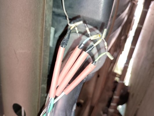
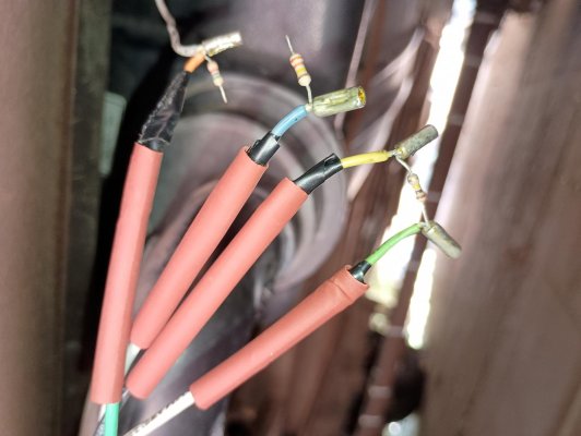
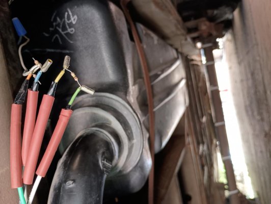
Anyway, after installing the new sensors in the newly drill holes, I used new wires to connect to the existing wires, which I should have just stripped and joined together and be done!! Instead I decided to remove a jacket that joined all 4 sensor wires together to investigate and see what was in there. Bad choice I made taking that jacket off!! because was in there are the 4 sensor wires and 3 small resistors.
I thought, ok let me put it back together and use electrical tape to insulate each wire/resistor separately just in case they are not suppose to be contacting each other; I should have taken some pictures right there and then!!, because as soon as I started taping them they came apart/detached from wherever they were soldered or attached!!
Now I have no idea where the end of the 2 resistors shown in the photo go to.
Does anyone know why there are resistors in the sensor wiring? Maybe to reduce voltage? If so to what?
Were they soldered somehow in a daisy chain?
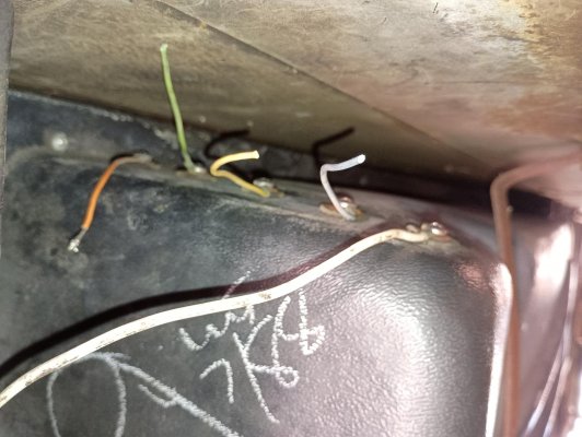
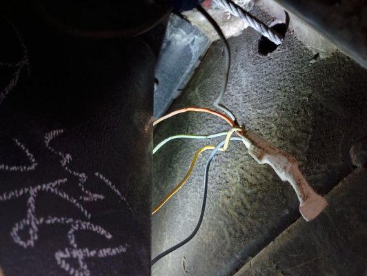
The Light Gray wire with the connector screw cap connects all 4 wires and then goes up thru the floor to the inside of trailer.
A while back another forum member had a tank sensor wiring question due to a broken wire at that Same/Similar attaching point.
Here is the link:
https://www.hilotrailerforum.com/f27...or-wires-5165/
Forum member Treeclimber suggested to him to "strip them back, twist them together and solder".
I supposed that would eliminate that plastic junction, although I think there may be some type of resistors in there also like in mine.
Would that be safe to do (join them together, no resistor)?
Would eliminating the resistors burn/short something out? What purpose are they serving?
I have attached some photos that may give you a better idea of what I'm talking about.
Thank you for any help with this and sorry for the long post.
I need help figuring out a wiring problem I'm having with my grey tank sensors wiring, (it's a problem that I created!!).
I replaced my grey tank sensors with Horst Miracle Probes, which was a little more work than I anticipated because I had to drill new 3/8 in. holes on the other side of the tank due to having no clearance at all between the tank and the trailer frame to remove the wiring and to remove the old sensors.
Anyway, after installing the new sensors in the newly drill holes, I used new wires to connect to the existing wires, which I should have just stripped and joined together and be done!! Instead I decided to remove a jacket that joined all 4 sensor wires together to investigate and see what was in there. Bad choice I made taking that jacket off!! because was in there are the 4 sensor wires and 3 small resistors.
I thought, ok let me put it back together and use electrical tape to insulate each wire/resistor separately just in case they are not suppose to be contacting each other; I should have taken some pictures right there and then!!, because as soon as I started taping them they came apart/detached from wherever they were soldered or attached!!
Now I have no idea where the end of the 2 resistors shown in the photo go to.
Does anyone know why there are resistors in the sensor wiring? Maybe to reduce voltage? If so to what?
Were they soldered somehow in a daisy chain?
The Light Gray wire with the connector screw cap connects all 4 wires and then goes up thru the floor to the inside of trailer.
A while back another forum member had a tank sensor wiring question due to a broken wire at that Same/Similar attaching point.
Here is the link:
https://www.hilotrailerforum.com/f27...or-wires-5165/
Forum member Treeclimber suggested to him to "strip them back, twist them together and solder".
I supposed that would eliminate that plastic junction, although I think there may be some type of resistors in there also like in mine.
Would that be safe to do (join them together, no resistor)?
Would eliminating the resistors burn/short something out? What purpose are they serving?
I have attached some photos that may give you a better idea of what I'm talking about.
Thank you for any help with this and sorry for the long post.