Elixir Converter Replacement

JackandJanet

Senior Member
Site Team
Joined
Jul 5, 2010
Messages
4,723
Location
Pine, AZ
I finally got sick of the OEM Elixir converter installed in my trailer and decided to replace it. I chose a Progressive Dynamics PD4045 converter based on its cost and features. It has 4-stage charging, easy to replace reverse battery fuses, an LED that tells you if those fuses have blown and was available from BatteryStuff.com for about $185, shipping and tax included.

I learned a great deal doing this replacement, and made some mistakes. I'll try to share both with you.

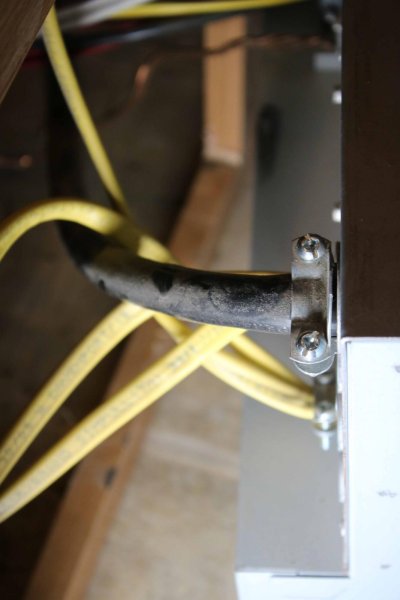
The first picture shows the Elixir converter pulled out from its mounting location under the left side of my couch. I chose to remove the couch cushions and the floor under the cushions to gain better access. The AC wiring is mostly on the left and the DC wiring is on the right.

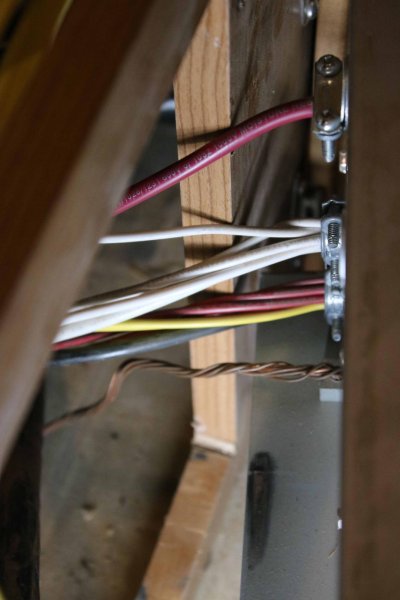
The second picture shows the AC wiring entry. The heavy black wire is the shore power cord and the yellow wires are ordinary house wiring to things like the Air Conditioner, Microwave, etc.

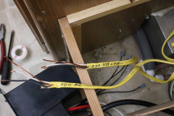
The third picture shows what is mostly 12V DC wiring, with one BIG exception! The bare copper stranded wire at the bottom is the AC current ground, that connects to a tab on the metal case. This is NOT part of the DC power circuitry and it must be kept separate!

Above the ground wire, is a bundle of colored wires. These are mostly positive 12V feeds to components, such as the water pump, interior lights, fan, etc. There is also a heavy black wire in this bundle and it is the 12V charging line to the battery. I did not understand that black wire properly and connected it improperly at first.

Above the colored bundle, is a bundle of white wires. These are the 12V negative lines that return current to the negative terminal of the battery. They are NOT "grounds", although they are often referred to that way. DO NOT combine them with the bare, AC ground wire!

The heavy red wire at the top is the +12V DC input from the Master Switch. Again, I did not fully understand this at first, which led to an incorrect hookup.

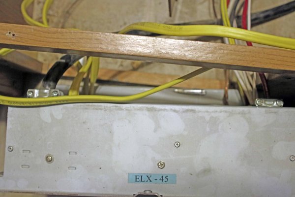
As I removed the old converter, I labeled all the colored wires. I simply wrote what the wires led to on the casings of the AC wires as shown in the fourth picture. I used magic tape as labels on the positive DC wires and wrote the fuse numbers they came from on them. I'll do the same on the corresponding wires in the new converter.

I think I'm limited to 4 pictures per post, so this will continue in the next one.
 

Attachments

  • 2. AC Wiring.jpg
    2. AC Wiring.jpg
    93 KB · Views: 92
  • 3. DC Wiring.jpg
    3. DC Wiring.jpg
    118.8 KB · Views: 94
  • 4. AC Wire Labels.jpg
    4. AC Wire Labels.jpg
    157.1 KB · Views: 88
  • 1. Elixir Pulled Out.jpg
    1. Elixir Pulled Out.jpg
    148.9 KB · Views: 110
Installation of the PD4045 - Continued

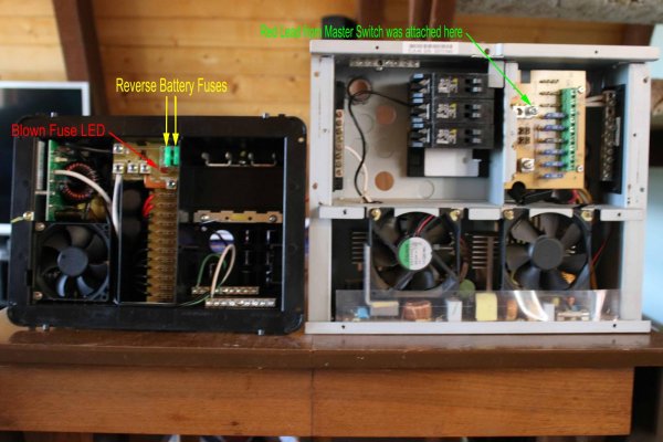
The first picture here shows a comparison between the PD4045 on the left and the Elixir on the right. The new converter is smaller, much lighter in weight, has an ABS plastic case instead of metal and offers up to 12 DC outputs vs nine on the Elixir. I've labeled the reverse battery fuses and the LED for them in the picture of the PD4045. Those fuses are hidden behind the fuse panel on the Elixir. and there's nothing that tells you they have blown, except that your battery will not be charged. The red wire from the Master Switch connected to the upper lug on the Elixir fuse panel. The smaller colored wires were attached to six fuse locations on the front of the panel and the white negative wires were attached to the buss bar at the right side of the case. The heavy black wire was hidden behind the fuse panel too, but was inline with the two hidden 30A fuses.

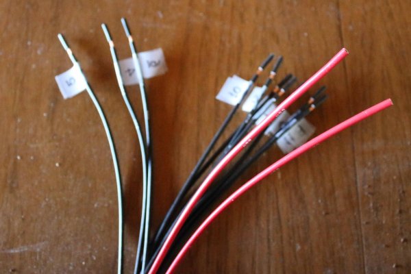
The second picture shows the way I labeled the DC output wires that were preinstalled on the PD4045. I chose to use six of the black, 20A capable lines. The two red ones could be used for circuits needing 30A, but they will not be used. I will simply tuck any unused wires out of the way.

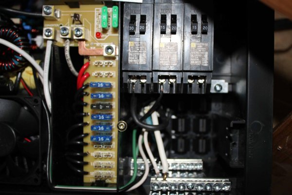
The third picture shows the DC and AC sections of the PD converter. I removed the fuses from the Elixir converter and installed them into the fuse holders I plan to use in the new converter. I also removed and installed the AC circuit breakers from the Elixir and installed them into the PD. Two of the CBs are wired in this picture. The 30A breaker is wired from the shore power cord and the leftmost 15A breaker is connected to the PD's converter section. In retrospect, it would have been easier to insert the black input wiring into the CBs BEFORE I installed the CBs into the case, but I did it the hard way.

If you look to the right of the heavy white wire connected to a lug at the left side of the DC circuit board, you'll see a white wire with a lot of writing on it. This was a DC negative wire I added, but later, incorrectly removed! That lug IS the -12V DC output!

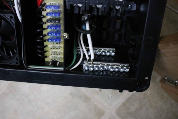
The fourth picture shows a detail of the AC "neutral" and ground buss bars. The neutral buss bar is the one in front. It receives all the white AC wiring. The bar in the back receives all the green ground wiring, AND, the bare AC ground wire I showed in an earlier picture. That grounding wire MUST be connected here to properly ground the 120V AC circuitry!
 

Attachments

  • 5. Comparison.jpg
    5. Comparison.jpg
    172.3 KB · Views: 136
  • 6. PD Wire Labels.jpg
    6. PD Wire Labels.jpg
    171.4 KB · Views: 92
  • 7. DC and AC Sections.jpg
    7. DC and AC Sections.jpg
    162.7 KB · Views: 108
  • 8. Ground and Neutral AC Busses.jpg
    8. Ground and Neutral AC Busses.jpg
    140.9 KB · Views: 98
Last edited:
Installation of the PD4045 - Continued

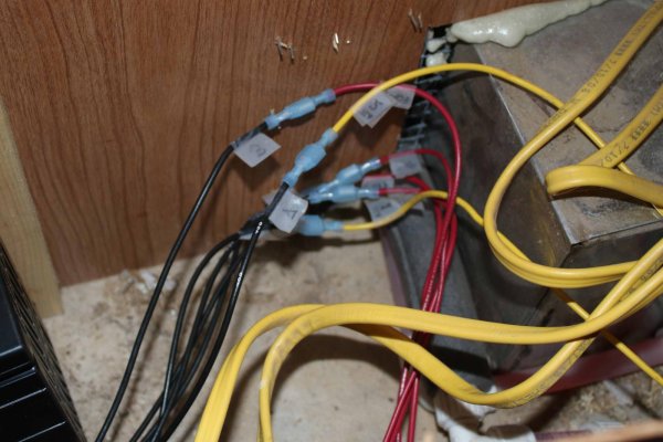
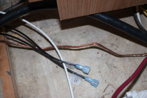
I've moved back to the trailer in the first picture here. It shows two insulated spade connectors I'm using to connect the +12V DC output to the trailer wiring. You're also seeing the -12V DC wire I installed (but incorrectly removed) and the AC ground wire which connects to the AC ground buss in the converter.

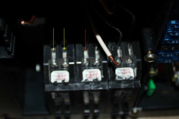
The second picture shows the underside of the circuit breakers that were installed in the converter. I found that I needed to turn the converter upside down to see the holes where the wires are inserted (at the head of the arrows) There is a wire already installed at the head of the red arrow, the holes at the two yellow arrows are empty. I'm sorry this picure is so poorly focused. Again, it would have been easier to insert the black wires into the CBs BEFORE putting the CBs into the converter case!

The third picture shows the completed spade connections for the DC wiring. I could have used wire nuts here, but I think spade connections are more secure. You can see how I labeled each wire here too.

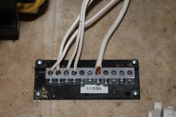
The Elixir converter has three buss bars, but the PD converter lacks the -12V DC bar. I simply removed the -12V DC buss bar from the old converter and screwed it into the floor of the trailer behind the converter. All of the trailer wiring that went to the old converter is shown connected here, in the fourth picture.

I SHOULD have attached the white negative 12V DC wire I installed in the converter to this buss bar too, but something I read on the internet made me think that wire was incorrect, so I removed it.
 

Attachments

  • 11. DC Connections.jpg
    11. DC Connections.jpg
    164.6 KB · Views: 65
  • 12. DC Negative Buss.jpg
    12. DC Negative Buss.jpg
    152.6 KB · Views: 65
  • 10. Wiring CBs.jpg
    10. Wiring CBs.jpg
    79.3 KB · Views: 70
  • 9. Spade Connectors.jpg
    9. Spade Connectors.jpg
    142.3 KB · Views: 61
Last edited:
Installation of the PD4045 - Continued

The first picture gives you some idea of the reduced size of the PD converter. I was testing the wiring here, and everything worked, except the battery was not receiving a charge when the converter was plugged in to shore power!

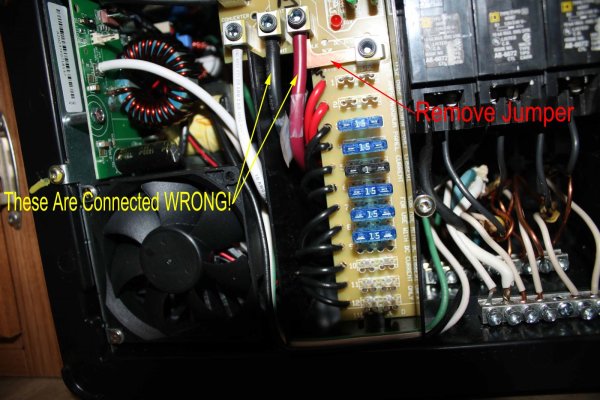
The second picture shows the problem, and it was the result of my research on this converter on the internet (and my misunderstanding of what I read). As you see, I've got the heavy black and red wires connected to the two lugs near the top of the fuse panel and I've left the copper jumper in place. The effect of this was to direct the charging current only to the positive terminal of the battery, there was no complete charging circuit to the battery's negative terminal.

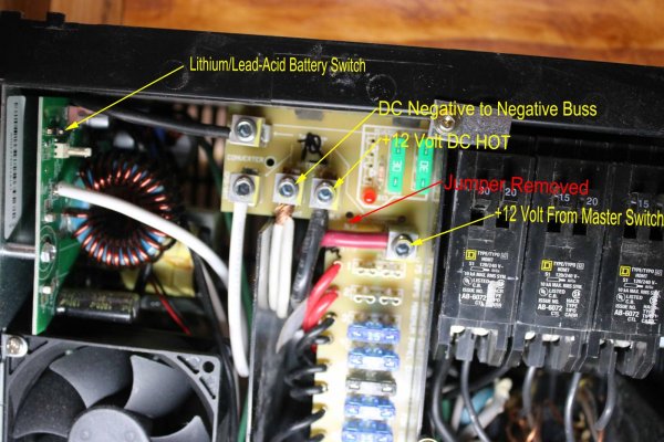
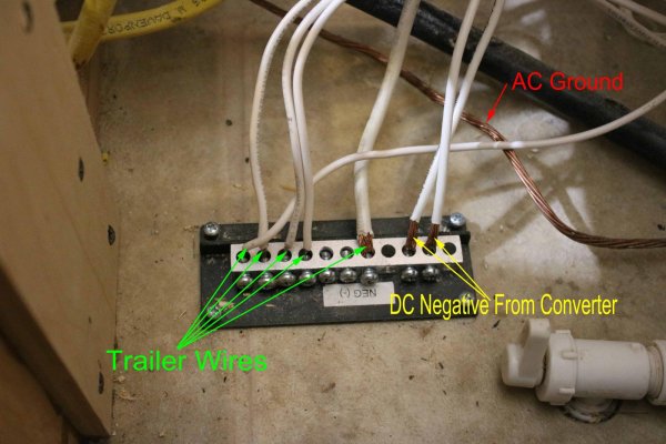
Finally, I worked out what was wrong. The heavy black wire is the charging output FROM the converter TO the battery's positive terminal. It is ALWAYS "hot" and could send power back to the fuses. The heavy red wire is the +12V power supply FROM the battery TO the fuse panel and is only "hot" when the Master Switch is in the "interior" position. The Master Switch in our trailers is what is referred to in the PD4045's installation instructions as an "external DC disconnect switch". So, the black wire must go to the upper right most lug (which must be separated from the fuses) and the heavy red wire is connected to the lug just above the column of fuses AFTER the jumper is removed. (You'll have to distort the jumper to get it out.) Then, the middle lug on the upper row is connected to the negative battery terminal through a wire to the -12V DC buss. This is all shown in picture #3, which is probably the most important one in this thread! You'll notice I've used two white wires to the -12V lug. It's because that circuitry needed #8 wire (which I don't have) and I had to substitute two #10 wires to get enough thickness.

In this third picture, I've also shown you the location of the teeny, tiny microswitch that you set for lead-acid or lithium battery charging. It is a "slide" switch, and you can feel it "click" when you move it, even though you can't tell it's position by looking at it.

Finally, picture #4 shows the completed wiring to the -12V DC buss. The paired wires from the -12V lug are attached at two points on the buss, since they would not both fit into one easily.

There's one more post to finish things off.
 

Attachments

  • 14. Opening Size.jpg
    14. Opening Size.jpg
    173.6 KB · Views: 64
  • 13. Wrong Wiring.jpg
    13. Wrong Wiring.jpg
    213.1 KB · Views: 82
  • 15. Correct Wiring.jpg
    15. Correct Wiring.jpg
    227 KB · Views: 94
  • 16. Completed Negative Buss.jpg
    16. Completed Negative Buss.jpg
    192.8 KB · Views: 72
Last edited:
Installation of the PD4045 - Last One

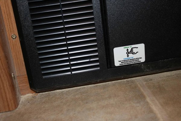
This is the front panel of the new converter and it shows a label for the microswitch you set for lithium or lead-acid batteries. The switch is moved forward for lead-acid.

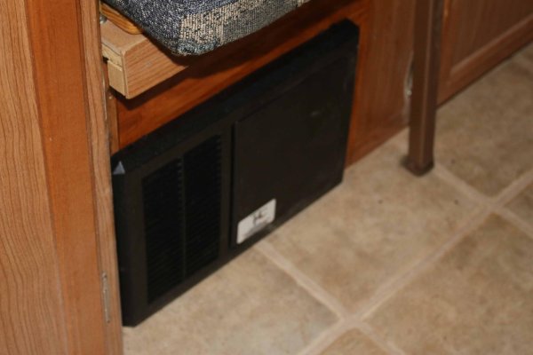
The second picture shows the converter installed. I used white pine to fill the space and stained it. It's not a perfect match, but below the couch, the difference is hardly noticeable.

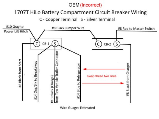
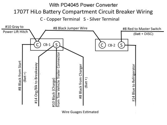
Now, there was something else that I figured out from all this. The two circuit breakers in my battery compartment were wired wrong at the factory!

The third picture shows the problem, and what has to be done to fix things. The way the black wire from the charger is connected to CB-2, it delivers unprotected power through the red wire to the fuse panel anytime the converter is connected to shore power. You can't move it to the copper terminal of that CB either, because then it would deliver unprotected power to the battery through the jumper! It HAS to be connected to the silver terminal of CB-1.

I'm showing the correct way these two CBs should be wired in the last picture. I've also labeled everything more clearly to show the function of each wire. In this setup, there is circuit breaker protection along ALL circuit paths.

I hope this thread will help anyone who wishes to swap out their converter. Even if you don't install a PD4045, as I did here, a complete understanding of the function of all the trailer's wiring will help you do the job properly.
 

Attachments

  • 17. MicroSwitch Label.jpg
    17. MicroSwitch Label.jpg
    223.1 KB · Views: 49
  • 18. Installed Converter.jpg
    18. Installed Converter.jpg
    112.3 KB · Views: 57
  • Old Primary Wiring.jpg
    Old Primary Wiring.jpg
    123.7 KB · Views: 79
  • Correct Primary Wiring.jpg
    Correct Primary Wiring.jpg
    141 KB · Views: 65
You did a great job of showing and explaining everything. Some things can get confusing, electricity is easier to figure out if you can imagine water going through pipes rather than wires. You should give the thread a sticky to keep it on top of the electrical menu.
 
Okey Doaks. Thanks for the kind words, Rich and you are absolutely correct about imagining DC current as water going through pipes. Voltage is pressure and current is volume. Resistance is like roughness or a restriction in the pipes.

AC current though, is not quite that simple. Still, for purposes of this installation, it was relatively straightforward as long as the ground was connected properly.

I'm sure much of what I posted is obvious to many of our members, bur I know there are some who are VERY reluctant to tackle anything electrical. I tried to make this thread accessible to them. (And, I also want to help remove the fear of making mistakes. I make them all the time and hopefully, learn from them.)

- Jack
 
Last edited:
Thanks!

This was super helpful. I just installed the exact same thing on my 1706, but couldn't figure out why DC was always on. Removing the jumper and putting the conductors in the right place via your photo did the trick. Thanks again!
 
Great! I'm glad it helped. The instructions that came with it were not a whole lot of help and a source I found online was confusing (or wrong), too. But, luckily, when I hooked mine up wrong, there was no damage, and I was able to figure out then what I needed to do.

Enjoy the new converter. It's a whole lot better than that Elixir thing.

- Jack
 
I'm looking forward to it! We've only owned the 1706 for about a month and we've already used it for about 3 weeks.

I did have one last question about the install if you have a moment. In the DC fuse stack, the top spots labeled 1 and 2 are empty. In the alternate instructions for this converter, it shows two 30 amp fuses there and calls them "reverse battery protection fuses" (https://www.progressivedyn.com/wp-content/uploads/2017/05/PD4045-TROUBLESHOOTING.pdf)

Should I install 30 amp fuses in those spots, or is it okay to leave them open like in your photos as well? Do you know what purpose they serve?

Thanks again!

Charles
 
The reverse battery protection fuses are NOT the ones they show in positions 1 & 2. The reverse battery fuses are the ones mounted vertically at the very top of the unit above the horizontal fuses in the fuse panel. They are shown correctly in the first picture of your manual, but I believe they are mislabeled in the second picture.

I left 1 & 2 blank because the wiring to it was heavier in my unit (red wires) and I did not need that capability for 15 Amp devices. Yours appear to be all black but they are showing 30 Amp fuses there. Possibly, those wires are heavier? Your unit appears to have had a couple other changes too - your "reverse battery" indicator is green - perhaps it is always on if the fuses are good. Mine is red and it comes on if a fuse has blown. You also have a third wiring buss under the circuit breaker holders, attached to the side of the unit. Mine did not have this and I used one out of the old unit that I attached to the floor of the trailer. Your directions are different than mine too.

It looks to me as if you could use fuse positions 1 & 2 for any of your trailer's 12V DC devices. Or, you could leave them blank like I did. My trailer had only 6 fused devices, so I left 6 positions empty - you can probably do the same.

- Jack
 
Last edited:
Progressive Dynamics Converter

I just completed the replacement of the old Elixir converter in my 2004 2205TL. A BIG THANK YOU to Jack for his detailed description and pictures of this swap. I had the help of a friend which made the install go much smoother. His extra pair of hands were extremely valuable. The most difficult part for me was the tight confines in the PD converter. As Jack's pictures show the PD is much smaller than the Elixir. My converter is located in the wall between the refrigerator and the sofa which made for a very tight work space. Follow Jack's instructions/insights and you will have no problems. Thanks again Jack !!
 
elixir converter replacement

Thank you for all these instructions. I was able to follow them and replaced my old Elixir with a PD 4045. Not to difficult I had to take the top cover off in order to rearange the wires.
 
Great! Glad you were able to make the switch, mail_pouch! I am MUCH happier with the PD converter! I think the Elixir was just a pile of junk.

- Jack
 
elixir converter replacement

I noticed when putting on the new labels that one of the 12 volt circuits was DSI, what does that represent?
 
I noticed when putting on the new labels that one of the 12 volt circuits was DSI, what does that represent?

Well - I did not notice this when I installed my converter, so I've done an internet search using the search string: "12V DSI". All I came up with was that it stands for "Direct Spark Ignition" and would be what the water heater uses to ignite propane for propane water heating. If this is correct, then THAT circuit would be the one to send power to the hot water heater ignition.

Now, I don't really know how important this is. I certainly just connected the water heater ignition randomly to the fuse panel, except that I put the proper sized fuse in that line. On which fuse position did you see the DSI spec?

This is the URL of the place where I read about DSI: https://www.popupexplorer.com/forum/index.php?topic=71221.0

There were several other references to DSI (water heater ignition) using that search string too, so I suspect that's what it is. I found nothing in the latest converter user manual about it.

- Jack
 

New posts

Try RV LIFE Pro Free for 7 Days

  • New Ad-Free experience on this RV LIFE Community.
  • Plan the best RV Safe travel with RV LIFE Trip Wizard.
  • Navigate with our RV Safe GPS mobile app.
  • and much more...
Try RV LIFE Pro Today
Back
Top